BuildYourCNC
LED Button Tactile Switch
LED Button Tactile Switch
Couldn't load pickup availability
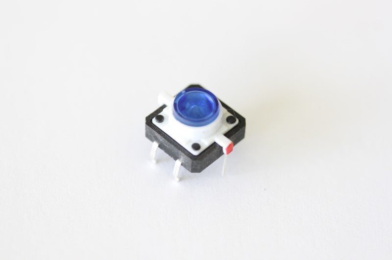
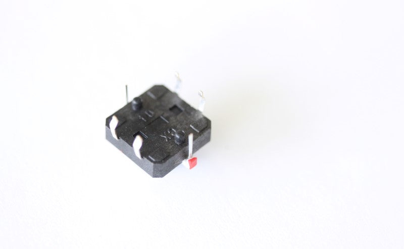
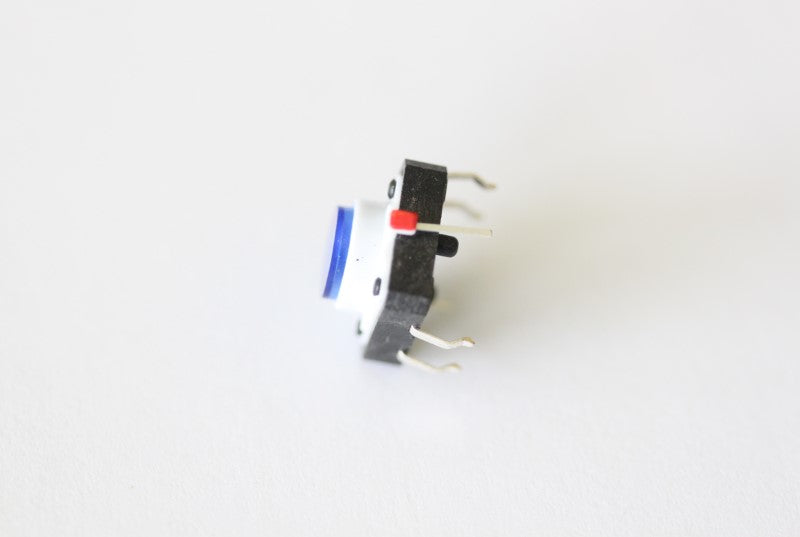
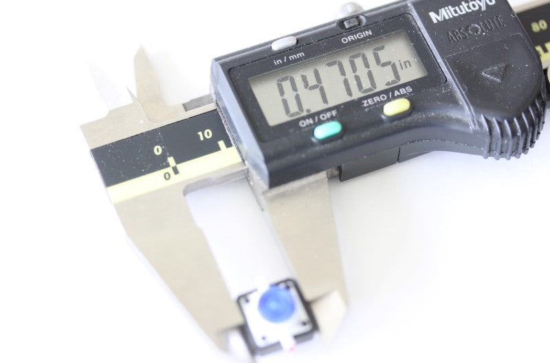
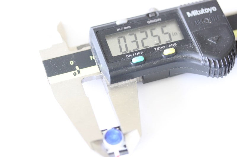
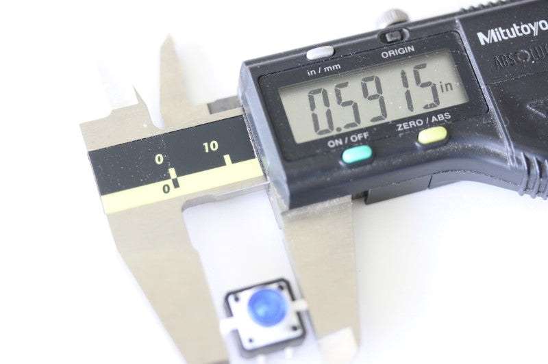
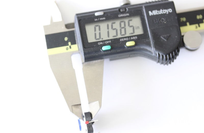
Push button switches are used to provide input to microcontrollers and electronics. Press the button to complete the circuit. This is just like the regular push button switch except it has an LED which can provide visual feedback. This is the type of tactile push button switch that has a momentary action which means, the switch is activated only when it is depressed. When the push button is released, the switch is disengaged. The LED is blue color. Specifications: Size: 12mm x 12mm x 7.3mm Mounting type: through hole Max Voltage: 12V Max Current: 50mA
Share
Questions & Answers
Have a Question?
-
How can I connect the Pokeys57CNC controller to a DRV8825 / A4988 expansion board?
The DRV8825 driver IC by TI (Texas Instruments) has two main connections called STEP and DIR. These are the two main connections that you need to use to connect to the Pokeys57CNC controller. You also need to connect the positive digital voltage pin (5V) from the Pokeys57CNC controller's motor connector to both the reset and sleep pins. The GND pin from the Pokeys57CNC motor connector is connected to the GND pin of the DRV8825 driver. The enable pin of the DRV88525 can remain unconnected. There is a trimmer potentiometer on the DRV8825 that can increase or decrease the amperage setting for the motor. Depending on the DRV8825 board you purchased, there may be two pads to determine the amp setting while turning the trimmer (in the voltage setting on your multimeter). The A1 and A2 is connected to one of the motor's coils and B1 and B2 is connected to the other motor's coil. There is a pin on the DRV8825 called VMOT that you will connect to the power supply (max 45VDC) and the GND pin next to the VMOT is the V- for the same power supply. I hope this helps. If not, please add additional information on this thread. Additional Information: I followed (to the best of my ability) the instructions provided to my original question, but I did not receive successful results. When I followed the instructions and connected the ground pin from the Pokeys57CNC motor connector to the DRV8825 / A4988 expansion board, it stops the communication between the Pokeys57CNC board & the motors 1-3 that I had working previously. The DRV8825 / A4988 expansion board will be the fourth driver I am connecting to the Pokeys57CNC. The previous three drivers are PoStep-60's if that helps understand the issue. Prior to hooking up the ground pin (I used pin 10 from the Pokeys57CNC motor connector) to the DRV8825 / A4988 expansion boards ground pin, I was able to see the power being applied via the red LED being illuminated on the DRV8825 board; after this new configuration the light is not turning on. With the new recommended setup, I used a heat shrink solder piece to add the shunt for the connection to the sleep pin. The connection to the sleep pin is where I believe my issues are stemming from. I must be connecting it to the incorrect pin (within the 9 pin layout on the DRV8825 / A4988 expansion board). Do you have any reference to the 9 pin pinout on the A4988 expansion board? I double checked the pinout provided on the Texas Instruments page, but it only gives clarity to the pinouts on the DRV8825 board itself. After reviewing their documentation, I tried connecting the 5v (pin 9 from the Pokeys57CNC motor connection that's split to connect with the reset pin on the DRV8825 / A4988) wire directly to the terminal on the DRV8825 board and that didn't work either. Any help or clarification you can provide would be greatly appreciated!


