Skip to product information
1 of 9

BuildYourCNC

Vacuum Regulator Pump Controller

Vacuum Regulator Pump Controller

Regular price $179.00 USD
Regular price Sale price $179.00 USD
Sale Sold out
Title
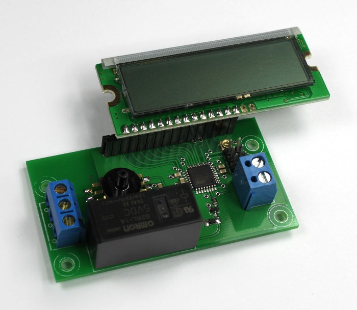
This vacuum regulator (manostat) will turn on a vacuum pump when the vacuum gets too low in the vacuum chamber or tank. The vacuum regulator will keep a specific range of vacuum in the vacuum chamber. If you need to hold a specific range of vacuum pressure, this vacuum regulator also called a manostat is the device that will do it. All you need to do is set vacuum range you desire and this vacuum regulator will control the vacuum pump to keep the pressure within this range. The vacuum regulator (manostat) allows you to control a vacuum pump, so you don't need to manually turn on the vacuum pump when the vacuum in the vacuum chamber becomes too low. Think of this vacuum regulator as a safe guard against having a vacuum that is too low. Before this device was developed, I needed to turn on and off the vacuum pump manually. The vacuum pressure controller features two trimmer potentiometers to adjust a low and high end thresholds to control a vacuum pump to maintain a range of vacuum pressure. The extreme ranges that this pressure controller can sense is -100 to 0 kilopascals or 29 to 0 inches of mercury (hg). An LCD is included to show the values of the high and low thresholds and the current sensor reading. The relay can be connected as NO (Normally Open) or NC (Normally Closed). . The relay that controls the vacuum pump can accepts up to 250V/12A of power. Overall function of this device: When the pressure is below the low end threshold, the relay will engage, turning on the device (vacuum pump) that is connected to the relay. When the pressure climbs above the high end threshold, the relay will disengage, turning off the device (vacuum pump) that is connected to the relay. Note: The LCD screen text can be oriented to face either direction.
View full details

Instructions

1
Step 1
This video demonstrates an improvement made to the vacuum pump controller. The values for the thresholds and the actual sensor inches of Hg is now in decimal form with a precision of 2 decimal places.
2
Step 2
This video describes the features of the vacuum pressure controller. All of the features are explained and demonstrated.
3
Step 3
The vacuum pressure controller requires 5 volts of power. This power can come from the computer via a USB cable, or a 5 volt power adapter. The controller requires very little current to drive the relay on this board (Relay coil: 80 mA with a coil resistance of 62.5 ohms). If a computer USB cable is used, cut the cable and expose the red and black wires from the cable. The other wires and shielding can be removed, or cut short as they are not used. For both a USB cable, or adapter, the +5V wire (red wire in the USB cable) is fastened inside of the terminal closest to the LCD. The GND (black wire in the USB cable) is fasten to the terminal farthest from the LCD.
4
Step 4
Adjust the low end threshold using a small screw driver at the left potentiometer trimmer. This will adjust the number labeled L: and is shown in inches of mercury (Hg). When the actual pressure is less than or equal to the low end threshold the relay will engage (send current to the coil of the relay and close the two terminals for NO-normally open operation.
5
Step 5
Adjust the high end threshold using a small screwdriver at the left potentiometer trimmer. The high end threshold is labeled as H: and is shown as inches of mercury (Hg). When the actual pressure in the pressure sensor is greater than or equal to the high end threshold, the relay will disengage, or opening the terminals for NO (normally open) operation).
6
Step 6
Use a tube that will fit over the pressure nozzle that has a diameter of 0.1165 inches (2.95mm). A silicone tube with a 1/16 inch inside diameter works well which stretches around the nozzle of the pressure sensor.
7
Step 7
Insert the tube over the vacuum pressure sensor nozzle. This tube will connect to the device that holds the vacuum or the line that is connected between the vacuum pump and the tank. Make sure to use a check valve between the vacuum pump and the tank (or container/device that will hold the vacuum). A check valve is a device that only allows air to travel one way. This will prevent the vacuum from escaping the tank back into the vacuum pump. The pressure sensor hole should be fitted onto the tube after this check valve, or fitted directly onto the tank.
8
Step 8
Use either an extension cord, or the power cable from the vacuum pump and remove the outside insulation. It is best to use an extension cord so that the main power cable for the vacuum pump is not damaged.
9
Step 9
Cut the black (live) wire in the AC cable and expose the strands. The live/black wire is used as this is the safest wire to pass through the relay.
10
Step 10
Insert one side of the black wire into the lower terminal. This terminal is the main terminal of the relay that will provide one side of the relay switch. Insert the other side of the black wire into the top position of the terminal. This position is the NO (normally open) position of the relay and will be open when the relay is disengaged (i.e. the two black wires will not be connected - open). When the relay is engaged, these positions will close (be connected). The middle terminal is a NC (normally closed) position with respect to the bottom terminal. Use this terminal if you want to reverse the on/off function of your vacuum pump.

Questions & Answers

Have a Question?

Ask a Question
  • What are the overall dimensions of the USB interface board? Is there a CAD model available?

    The dimensions for our USB breakout board are: L: 2.745"/ 69.723mm W: 2.244"/ 56.9976mm H: .501"/ 12.7254mm Currently we do not have a CAD model on hand.

  • Can I get the circuit diagram of the pressure controller?

    Here is a list of videos on my designing the vacuum controller/sensor circuit: https://www.youtube.com/watch?v=bm888ntJiVs https://www.youtube.com/watch?v=hYZ2Sw4SeTA https://www.youtube.com/watch?v=8wCrMzrPoeo https://www.youtube.com/watch?v=-M7tiNmgTrM https://www.youtube.com/watch?v=o3eo23OmjtQ https://www.youtube.com/watch?v=PJO_XoLL6lQ

  • I accidentally put 12vdc to the controller and now the display does not work. Can this be repaired?

    The 12VDC applied to the input voltage terminals most likely damaged the microcontroller, the LCD, and the vacuum sensor. It can be repaired, but the repair will cost more than a new vacuum pressure controller.

  • I need a similar device with slightly different operating parameters/features: push button to activate pump initially, high set point turns off pump and starts a 30 sec timer, if low set point triggers during window activate Red LED else activate Green LED. Can you assist with this?

    I would not have a problem with modifying the design; however, the change you are requesting would require a large batch purchase since the PCB design would require modifications and a new batch of PCBs would need to be purchased.

  • What sensor is used and what is the resolution of the sensor?

    The pressure sensor used in this controller does not have a specific resolution since it is analog; however, the microcontroller used in this controller receives the information from the sensor using an ADC (Analog to Digital) converter. The resolution through this process is 10-bits. A 10-bit number is from 0-1023 (1024 possible values). The accuracy of the sensor is 1.5%.