


1
/
of
16
BuildYourCNC
Adjustable Rotary Limit Switch
Adjustable Rotary Limit Switch
1 review
Regular price
$7.99 USD
Regular price
Sale price
$7.99 USD
Unit price
/
per
Shipping calculated at checkout.
Couldn't load pickup availability
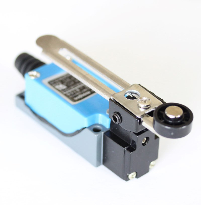
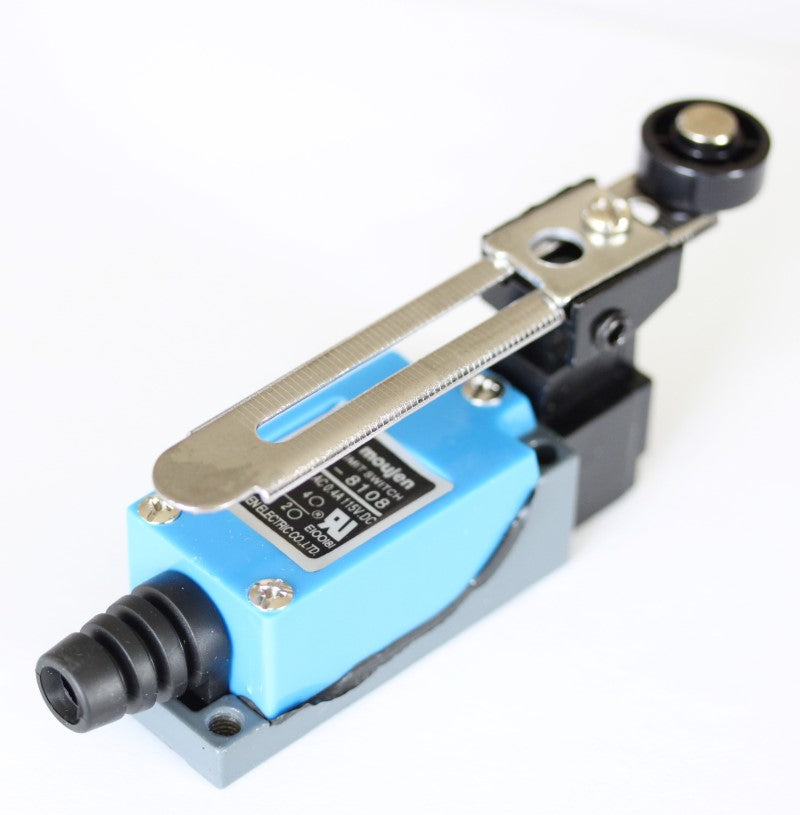
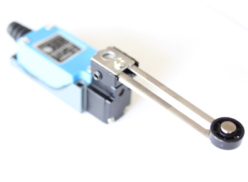
Versatile Rotary Limit Switches for CNC Applications
Product Features
- Rotational Action Design: The lever arm can be positioned to allow switch actuation without interfering with the triggering structure
- Adjustable Lever: Rotation angle can be adjusted up to 90 degrees
- Free-Spinning Wheel: Located at the end of the lever to prevent hangups when moving in reverse after actuation
- Electrical Rating: Handles up to 5A at 250 volts (compatible with standard 5V digital signals or higher voltages)
- Easy Connection: No soldering required - uses convenient screw terminals
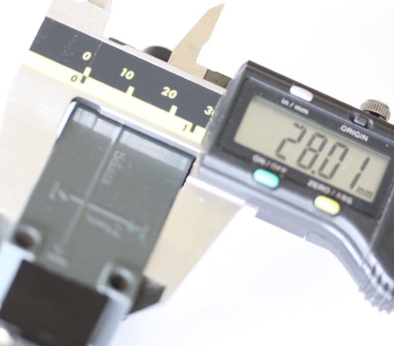
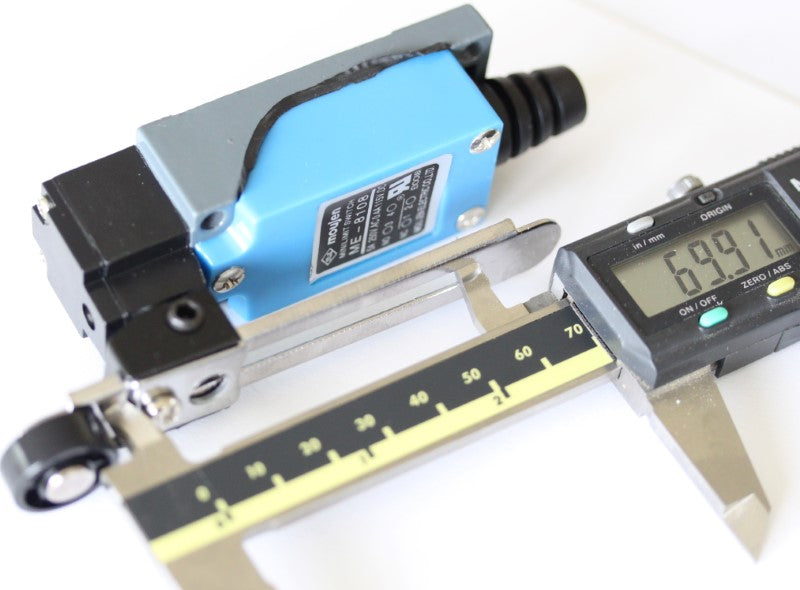
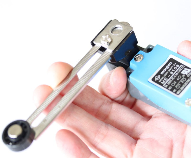
- Mounting Dimensions: Holes located at the back, measuring 21mm on center (width) and 56mm on center (length)
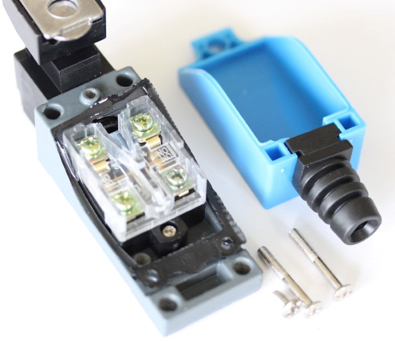
Terminal Configuration
- Normally Open (NO): Connect through terminals #3 and #4 (closest to the lever arm)
- Normally Closed (NC): Connect through terminals #1 and #2 (closest to the cable strain relief)
Installation Guide for Mach3 USB Controller
Required Materials
- Shielded cable with two conductors (22 or 24 AWG recommended)
- 24VDC power supply
Wiring Instructions
-
Prepare the Limit Switch:
- Remove the terminal cover to access the connection points
- Identify the NO terminals (marked between the terminal pairs)
- Connect your cable to the NO terminals (#3 and #4)
-
Cable Considerations:
- Use shielded cable to prevent interference with CNC controller input signals
- The shield and ground wire must be connected together
- If using cable with more than 2 conductors, ground all unused wires to prevent antenna effects
-
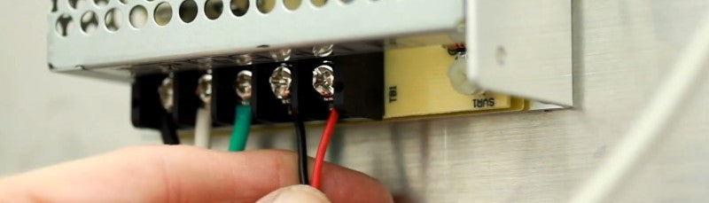
Controller Connection:
- Connect the signal wire (red in example) from one NO terminal to IN1 on the Mach3 USB controller
- Connect the ground wire (black), any unused wires, and cable shielding to the DCM terminal
- For multiple switches, a terminal strip can be used to accommodate connections to DCM
-
Power Supply Connection:
- Use a 2-conductor cable (shielding optional) between the 24VDC power supply and controller
- Connect V+ from power supply to 24V terminal on controller
- Connect V- (COM/GND) from power supply to DCM terminal on controller
-
Testing and Adjustment:
- Test the switch function with the machine part that will engage it
- Adjust lever length using the securing screw if needed
- Adjust lever angle using the allen set screw as required
- With default configuration, the switch should engage the reset function in Mach3
Connecting Multiple Switches
- Multiple switches in NO mode must be connected in parallel
- Connect one side of each NO terminal to IN1 (or to another switch on the same input)
- Connect the other side of each NO terminal to DCM (directly or via terminal strip)
- Test each switch to confirm proper function
Share


J
Jack Connelly I found this switch online and it looked similar to the height limiter switch on the hydraulic car lift in my garage. The existing switch failed causing some damage. Turns out the new switch is almost identical to the old. It's been working great
Hi Jack — really glad it worked out! A hydraulic car lift is a great application for this switch and it's good to know the fit was nearly identical to the original. Thanks for taking the time to share that — it'll help other builders who are looking for a reliable replacement in similar setups.