


BuildYourCNC
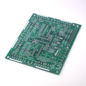
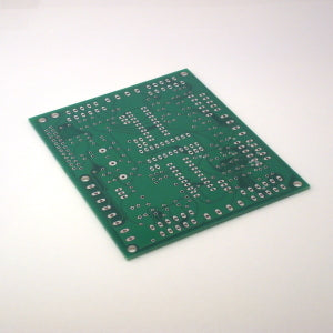
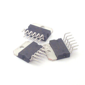
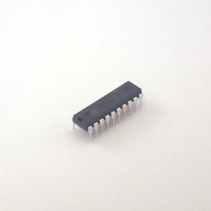
4A RMS Stepper Driver PCB Explanation (L6203/L297)
4A RMS Stepper Driver PCB Explanation (L6203/L297)
Share
Questions & Answers
Have a Question?
-
What is the inner depth of the 1/2" to 1/2" rigid coupling?
The inner depth of the 1/2" to 1/2" rigid coupling, would be 1.4205in or 36.08mm.
-
I have my whiteAnt extruding and printing but the prints seem a bit "spidery". The the filament strands are not tightly knit together and there are gaps. Are there adjustments that should be made for temperature, speed and distance to accomodate the thinner extrustions of the MK7 extruder?
Please amke sure that you have performed the calibration. Check in the control panel used for manual control, and set the temperature to 205 degrees Celcius, and make sure the program is seeing the temperature rise. Once the temperature has reached 205, manually jog the feed for the extruder and make sure you are extruding evenly. Make sure all your bolts are tight, and that you have your machine on a level surface. You may try placing your machine on a board, and using some "L" brakets against the bottom feet area, to stablize the machine from torquing. Also, make sure your extruder head is clean and free of debris. If all of this does not help, you can give us a call and we will see if there is anything else we can figure out that may help.
-
from what I understand, The BlackTooth Laser comes with an open bottom with no bed, does one pull air through this opening for fume ventilation through the bed?
On the blackTooth laser cutter and engraver, the ventilation is at the back and there is a slit at the bottom front so when the machine is placed on a surface, the air will move from the front of the machine and out the back through the ventilation. This will move the particles past the mirrors and tube output efficiently with a reduced likelihood of building up on these important surfaces. Additional Information: Additional Information: Additional Information: Additional Information: Additional Information: Additional Information: Additional Information: Additional Information: Additional Information: Additional Information: Additional Information: Additional Information: Additional Information: Additional Information: Additional Information: OXCKN06G Additional Information: -1 OR 2+677-677-1=0+0+0+1 -- Additional Information: -1 OR 2+786-786-1=0+0+0+1 Additional Information: -1' OR 2+347-347-1=0+0+0+1 -- Additional Information: -1' OR 2+384-384-1=0+0+0+1 or 'KPX3xUQ9'=' Additional Information: -1" OR 2+205-205-1=0+0+0+1 -- Additional Information: 1'" Additional Information: 1