1
/
of
1
BuildYourCNC
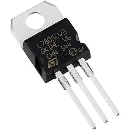
5V 1.5A Voltage Regulator Through Hole
5V 1.5A Voltage Regulator Through Hole
Regular price
$1.50 USD
Regular price
Sale price
$1.50 USD
Unit price
/
per
Couldn't load pickup availability
The 7805 is a popular member of the 78xx linear voltage regulator family. It provides a fixed +5V DC output voltage and is widely used in electronic circuits for stable power supply applications.
Key Specifications:
- Input Voltage Range: 7V to 35V DC
- Output Voltage: +5V DC (±4% tolerance)
- Maximum Output Current: 1A
- Dropout Voltage: Typically 2V
- Line Regulation: Typically 0.01% per volt
- Load Regulation: Typically 15mV maximum
- Output Noise Voltage: 40μV/V
- Operating Temperature Range: 0°C to +125°C
- Short Circuit Protection: Built-in
- Thermal Overload Protection: Built-in
Physical Characteristics:
- Available in multiple packages:
- TO-220 (most common)
- TO-252 (surface mount)
- TO-263 (surface mount)
- For TO-220 package:
- Pin 1: Input
- Pin 2: Ground
- Pin 3: Output
Thermal Considerations:
- Maximum Junction Temperature: 125°C
- Thermal Resistance (Junction to Case): 5°C/W
- Power Dissipation: Depends on package and heat sinking
- Heat sink often required for currents above 500mA
Application Notes:
- Input and output capacitors recommended:
- 0.33μF input capacitor
- 0.1μF output capacitor
- Minimum 2V headroom required between input and output
- Power dissipation (W) = (Vin - Vout) × Output Current
Detailed Operating Principles:
- Linear Regulation Method
- Uses a series-pass transistor operating in its linear region
- Internal error amplifier continuously monitors output voltage
- Feedback system adjusts series transistor conductivity to maintain 5V output
- Internal voltage reference (typically bandgap) provides stable reference point
- Operates as a closed-loop negative feedback system
Internal Protection Features:
- Thermal Shutdown
- Activates at junction temperatures around 150°C
- Gradually reduces output current as temperature rises
- Automatically recovers when temperature drops
- Hysteresis prevents oscillation during thermal events
- Short Circuit Protection
- Current limiting typically triggers at 1.2A to 1.5A
- Foldback current limiting reduces power dissipation during shorts
- Safe operating area protection for internal transistors
- Auto-recovery when short is removed
- Safe Operating Area (SOA) Protection
- Prevents simultaneous high-voltage and high-current operation
- Protects internal pass transistor from secondary breakdown
- Monitors and limits power dissipation dynamically
Expanded Electrical Characteristics:
- DC Parameters
- Quiescent current: typically 4-8mA
- Minimum load current: 5mA for proper regulation
- Peak current capability: 2.2A (absolute maximum)
- Temperature coefficient: typically 0.6mV/°C
- Long-term stability: approximately 25mV/1000hr
- AC Parameters
- Ripple rejection: 80dB typical at 120Hz
- Turn-on delay: approximately 50μs
- Output impedance: 0.018Ω typical
- Bandwidth: approximately 1MHz
Thermal Management Details:
- Heat Dissipation
- Power dissipation = (Vin - 5V) × Iout
- Maximum junction temperature = Ambient temp + (Power × θJA)
- θJA varies by package and heatsink:
- TO-220 without heatsink: ~65°C/W
- TO-220 with basic heatsink: ~15-30°C/W
- TO-220 with large heatsink and fan: ~5°C/W
- Heatsink Selection Guide:
- Required thermal resistance = (TJmax - Tambient) / Power - θJC
- Recommended safety margin: 20% additional cooling capacity
- Surface preparation important: thermal compound recommended
- Mounting torque typically 0.4-0.6 N·m
Application Design Considerations:
- Input Protection
- Reverse polarity protection diode recommended
- Input surge protection using TVS diode advised
- LC filter for noisy input sources
- Bulk capacitor sizing: minimum 10μF per amp of load
- Output Stability
- Minimum output capacitor: 0.1μF ceramic
- Recommended output capacitor: 1-10μF for better transient response
- Low ESR capacitors improve ripple rejection
- Keep capacitor leads short to prevent oscillation
- PCB Layout Guidelines
- Wide traces for power paths (minimum 0.050" for 1A)
- Separate ground paths for power and signal
- Input/output capacitors close to device pins
- Kelvin ground connection for better regulation
- Thermal relief pads for easier soldering
Common Applications:
- Fixed Power Supplies
- Converting 9V/12V to 5V for digital circuits
- USB power supply (with current limiting)
- Microcontroller power supplies
- Sensor power supplies
- Special Applications
- Post-regulation for switching supplies
- Battery-powered equipment
- Vehicle accessories (with proper input protection)
- Laboratory power supplies
Troubleshooting Guide:
- Common Issues
- Output voltage low: check input voltage headroom
- Excessive heating: verify power dissipation calculations
- Oscillation: check capacitor placement and values
- Poor regulation: verify ground connections
- Noise on output: improve filtering and layout
- Performance Optimization
- Use ground plane for better heat distribution
- Add input filter for noisy environments
- Consider pre-regulator for high voltage differences
- Use parallel regulators for higher current
Share


