Step 3 - CNC Z-Axis Part 1
Share
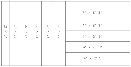
Illustration shown is the cut measurements for the first board. The cuts will be used for various parts of the machine including the z-axis, y-axis and a part of the x-axis. The cuts that measure 2' 3" in length will be used later on for a part of the y-axis and gantry supports. Save them for now. I have decided to go with aluminum angles instead of round bars to serve as rails. The beginning of the video shows an example of what I'm talking about. These angles will be able to secure itself around the edge of an MDF board allowing no play or bending. It also brings the cost way down. If you are a little skeptical of the aluminum angles, you can still go with the round bars, or maybe steel angles, however, these aluminum angles I feel will be superior to the round bar approach. In addition, the measurement for the back of the z-axis (supporting the two linear bearing supports) is not the correct length at 5.5". The fourth video explains the correct method to get the length in a more logical way. What is a Z-axis you ask? Do you remember 4th grade geometry? I only remember using the x and the y axis in that class, but it's the one in the 3rd dimension. Still confused? Ok... for the sake of simplicity, I will use the CNC machine as an example. Pretend you are looking at a router... Got the image in your head? Ok, imaging that the router is moving up and down... up towards the sky and down towards the ground... all with the bit pointing downwards of course. And if you didn't know, the bit is the thing in the router that spins and cuts stuff. Well, the up and down motion is motion on the z-axis. The x axis moved forward and backward, and the y axis moves left and right. I hope that helped... back to the build.
